Measurement principle of Birefringence Measurement System PA/WPA series.(2/4)
Four articles explain the understanding of birefringence and the measurement principles and features of our equipment.
Basic structure of Polarization Imaging Sensor
Microscopic size polarization filters are integrated and placed in front of a CCD image sensor
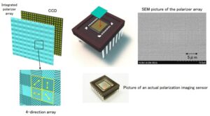
Please also see this page. About Special Image Sensor Manufacturing Technology
Principle of Polarization Imaging Sensor Technology and Measurement
Computation of polarization information from intensity at 4 neighbor pixels
[Relation between input polarization and intensity pattern]
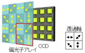
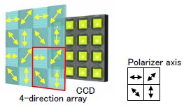
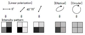
[Computation principle ]
Intensity is supposed to describe a sinusoid.
By knowing only 4 points of the curve, it is possible to recover the whole set of information for any input polarization.
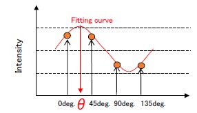
Polarizer angle
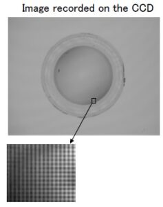
Intensity pattern is linked to the state of polarization at each location
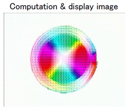
Birefringence data (phase shift and axis orientation) is present at each point as quantitative data.
Measurement example: lens
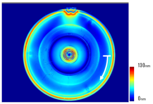
Phase shift distribution
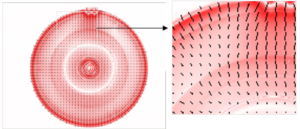
Axis orientation
・Detailed quantitative evaluation and comparison is possible between multiple sets of data.
・The slightest differences between two sets of data are easy to spot on displayed images.
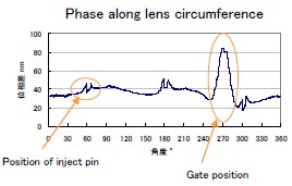
Phase along lens circumference
Continue to next page
Category
- #Birefringence & stress strain measurement solutions
- #2-D Birefringence Measurement System
- #Birefringence Measurement System
